First, note that the pictures in this how-to were taken while adding a memory chip; if you want to replace the main defective chip just follow the this instructions and you will most likely be able to start replacing the faulty chips.
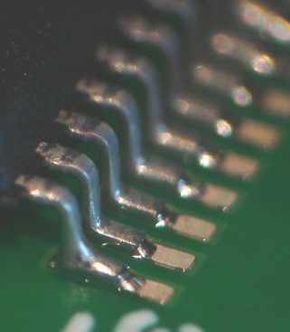
In this example , the dram chip is a TSOP package which have gull-wing metal leads and its easy to desolder the chip from the PCB board. Adding a new chip to the DIMM PCB board is simple since you only need soldering iron with a fine tip to get the job done.
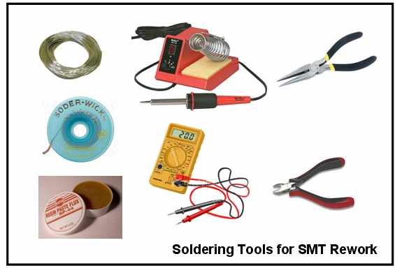
Gull-wing lead frames , easy to rework with standard soldering tools.
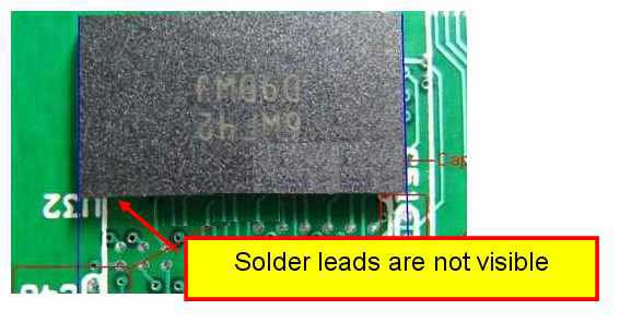
However, for reworking BGA chips, it will require specialized rework equipments to remove the BGA device and to replace the components. BGA rework is alot harder than surface mount TSOP devices. See illustration of a DIMM using BGA device, soldering leads are not accessible.
(Side-View BGA device connection leads are under the device,not possible to rework with soldering tools)
Here are the tools needed in this project:
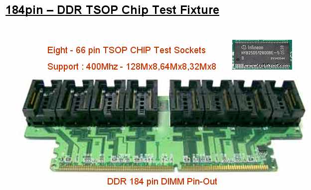
In this project, the target chip is a 512 MB DDR DIMM memory, using 64Mx8 (66 pin TSOP) memory chips ( Infineon ) DDR chip.
How to get a new working chip ?
You can get an extra memory chip from other defective DIMM memory, make sure you marked the good working chips. Most DIMM memory module manufacturers uses the following fixture to test chips before soldering the chips on the PCB board.
Notice the TSOP test fixture looks similar to a DIMM module except it has test sockets for inserting chips.
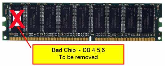
Extracting known bad memory chip ( marked X) from the DIMM module. This module have been tested with a CST SP3000 DDR Tester and chip U1 is bad.
DDR DIMM - 512Mb ( 64Mx72) Total 9 chips
If you already have a known good memory chip ,it is safe to skip this section and proceed to "Preparing to solder the second chip".
Make sure you do not mixed different brands of memory chips on the same DIMM module, otherwise the module will not operate properly.
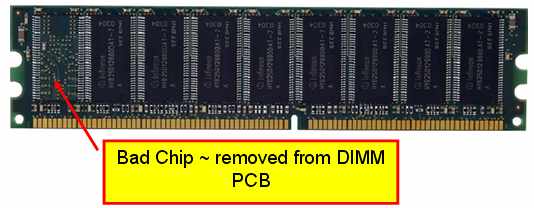
Disassemble the bad chip U1.
Hold down one side of chip and gently apply some heat to desolder it.
Attention!
Do not over-heat chip with soldering gun/iron.
Here's the 64Mx8 DDR memory chip. Pins will be dirty after removal (tin + rosin).
Clean it so there are no short circuits. It is now ready to use!
- Preparing to solder the second good chip
- Disassemble the faulty chip and secure it to a table, with the free soldering place face up.
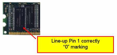
- The "o" symbol marks position of first pin of memory chip! This is very important! You can't turn chip around during soldering. The chip MUST be correctly - aligned! Take a look at the pin 1
- Clean the free soldering place on the circuit board of the with alcohol, if necessary.
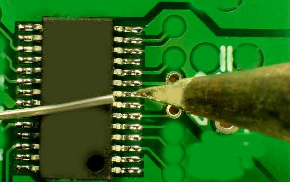
Soldering the chip
Apply tin to solder the chip legs to the board. This is the most dangerous and difficult part as the pins are so small and close that it is very easy for solder to bridge across the pins.
Tips:
Use as little tin as possible. Soldering areas are just covered - it should be enough.
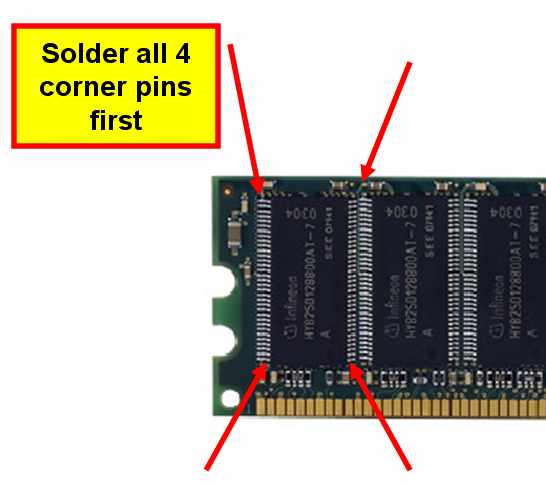
Place the DDR chip very precisely on the soldering pads.
Solder first and last pin, then check if location of chip is correct. If it's OK, then solder the rest of the pins - side by side.
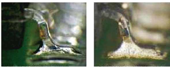
example of good solder joints
STOP and CHECK with multimeter and magnifying glass , MAKE SURE that there are no short-circuits between chip legs.
Testing the DIMM module
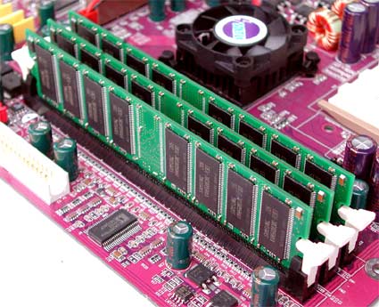
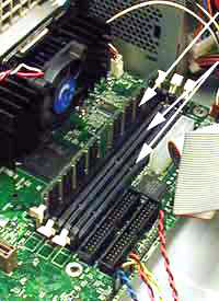
For a final test, load the DIMM module on the PC motherboard and test if able to boot-up
If everything works fine, If something wrong happens, check for short-circuits on the soldering work you've made.
Final result and test on the motherboard.
For details on how to use Diagnostic cards for testing memory module,
check out this article on " Memory Test Software Review".
By: DocMemory
Copyright © 2023 CST, Inc. All Rights Reserved