Tuesday, October 13, 2009
What is LR-DIMM or LRDIMM ?
Today, using RDIMMs, a typical server system can accommodate up to three quad-rank 16GB RDIMMS per processor. However, that same system can support up to nine quad-rank 16GB LRDIMMS per processor, pushing the memory capacity from 48GB to 144GB.
Load reduced DIMM (LRDIMM) is another new memory technology in development. Designed with a buffer chip (or chips) to replace the register to help minimize loading, the LRDIMM is targeted to increase overall server system memory capacity and speed using a memory buffer chip or chips as opposed to a register.
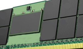
( Large rectangular memory buffer)
Before we dive deep into LR-DIMM, lets refresh some key features on DIMM memory which is a Dual Inline Memory Module. DIMM stands for Dual Inline Memory Module. It is the RAM memory we found in our desktop computer. It consists of a few black chips (IC) on a small PCB. It stores our file and data temporally when we turn on our computer. “Dual Inline” refers to pins on both side of the module. We generally call them “gold fingers”. I used to put 4 of these sticks into my old 486 computer to reach the maximum allowable memory of 16MB. With the change of time and technology, I now found that I still have 4 sticks of memory in my new computer but the total memory is 16GB instead. Not only the memory capacity has increased, I also found that my memory now is 200 times faster than the memory in my 486 computer.
Memory loading in a consumer computer
With the 16GB of DDR3-1333Mhz memory in my computer, I now can play online games, stream movie and draw my 3D graphic pictures on the screen. It is just slick! Don’t I need more? Yes, I would like to share my movies with 3 of my friends. I would like to pass picture files to my cousin in China and I also want to watch the Space Shuttle Launch. I will never run out of memory appetite. My next question is: Why can’t I put 6 sticks of memory into my computer?
Wait a minute! You just cannot keep adding memory into your computer without any penalty. At 1333Mhz (1.3GHz), noise gets involved. It generally is something called the signal integrity or signal reflection issue. At a point, the accumulated noise in the system would render the system not operable.
At high frequency, there is also something called “loading factor”. Each memory chip (IC) has input capacitance that tends to suppress the high frequency signal. Generally, each chip has about 3 to 5 pf of input capacitance. The more chips on the module, the more accumulated capacitance will weaken the signal to an in-operable state.
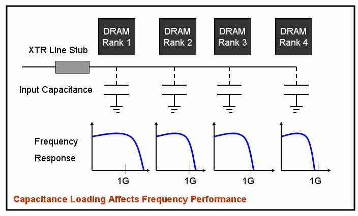
(Graphical illustration: Input capacitance increases the loading factor at high frequency)
To solve the “loading factor” problem, the PC designer introduced “multiple memory channels”. Some are dual channel and some are triple channel just to let you maintain the large number of memory in your computer.
Memory loading in a server computer
Server computer further complicates the issue. Since server runs multiple applications simultaneously, it is best to have all the necessary data running on the active background all the time. That calls for tremendous amount of memory running dynamically at high speed and high band width. But the question is how to achieve that?
Examining a regular memory module (unbuffered DIMM), we realize different groups of input lines on the same module has different loading. For example, those go to the address and control instruction lines are connected to more chips in parallel in comparison to the data bus lines. The data bus lines are usually only connected to either 1 chip or 2 chips versus the other lines can be connected to as many as 16 chips. Therefore, the question is if we can add a logical driver (buffer) chip in between the input and the address and control bus. It would even be better if this chip can also be used to line up all the address and control line signals. A register chip is, therefore, used to deliver the proper function. It is to increase drive power and keep the bus signals lined up.
Registered DIMM. Bandwidth and scalability
This register chip really does wonders. It keeps the signal strong and also synchronized the timing between lines. Since the clock signal is repetitive, it can also be strengthened using a phase lock loop re-driver. A phase lock loop re-driver is also called a zero delay clock driver. It re-generates clock signal in time synchronization to the original clock signal. Using this method, several identical clock signals can be generated from the original clock source and thus multiplies the drive power of the origin repetitive clock source.
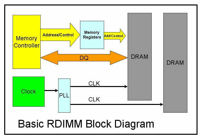
(Graphical illustration: Register DIMM Block Diagram)
Speed evolution limits the number of modules in a server system
Since the invention of the registered module, it kept the server industry going for years until once again the increase in operational frequency had hindered the system memory capacity (number of modules per system) again.
There comes the FB-DIMM with serial input and parallel output
Intel had invented the Fully Buffered DIMM to solve the above problem. It put a big driver chip in the middle of the DIMM module. This buffer chip accepts a high frequency serial signal input. Inside the chip, it converts this serial signal to parallel signal and re-drive the memory chips (DRAM) from there. Ideally, this approach reduces the physical number of signal lines at the input of the DIMM and therefore un-cluttered the physical system wiring. At the same time, it increases the number of module per system.
When FB-DIMM run out of steam, LRDIMM comes into the picture.
While Fully-Buffered DIMM was originally a good idea, the industry soon found that it has implementation problems. First, the serial input frequency has to be 4 times higher than the memory clock frequency. This puts it into the microwave frequency range and is a whole new page of technical difficulties. The signal weakening issue at high frequency is amplified to a difficult to control stage. Besides, the higher serial input frequency also increases the heat generation to an unacceptable point. Smart engineers soon announced the alternative approach, the LRDIMM.
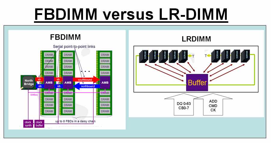
(Graphical illustration: Block Diagram FB-DIMM vs LRDIMM)
LRDIMM is Load Reduced with high fan-out and bi-directionally buffers
All lines are buffered. The LRDIMM (Load Reduced DIMM) works very similar to a Registered DIMM. It buffers the address and control signals through register logic. It re-drives the clock through Phase Lock Loop. The difference is that it also buffers the data lines through bi-directional drivers. This way, all the signal lines are truly “fully buffered” in the parallel fashion.
Pros and Cons of LRDIMM, technical point
Through the full buffering of all signals, you can double the number of DIMM in a system using the LRDIMM re-drive method. With the addition of the new 4 rank modules and dual die chip, you can reach up to 16GB per channel with LRDIMM in today’s system. Together with the new 4 channel system construction, 8 modules and 64GB memory population total can be achieved. Since the serial approached is abandoned, the heat and power dissipation problem no longer exist.
However, I do see one short fall on LRDIMM. Data line latency would increase. Write/Read turn around time will be required. There will be system with 2T and 3T practical latency. Luckily, most of the applications in server system are consecutive reads where write is not very frequent and therefore would not affect the average system performance.
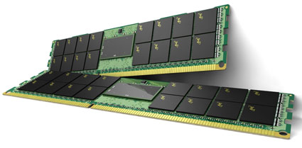
(Picture of LRDIMM: LRDIMM enhances server system performance)
Cost and benefit analysis, financial view
Since LR-DIMM will be a JEDEC standard, it is widely support by the industry. Cost will be driven down by volume production and multiple sources. Presently, there are many companies supporting the creation of new standard. That includes DRAM manufacturers, logic buffer chip manufacturers as well as memory module designers and infrastructure providers.
Conclusion
Looks like LR-DIMM will definitely be the next generation server module. Since it is scalable following the DRAM chip roadmap, it will cover from the DDR3 into the DDR4 DRAM generation. Beyond that, nobody would know if bigger and better technology will surface. Micron is currently sampling an 8GB LRDIMM with select enablers. Mass production of its 16GB LRDIMMs is expected to begin in 2010.
One thing for sure is that CST, Inc. (Simmtester.com) will be here to support the testing with low cost LRDIMM testers.
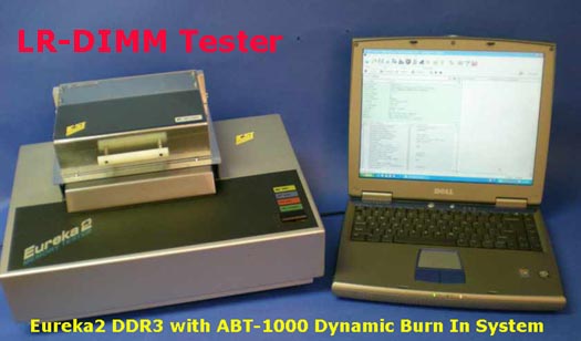
(Picture of CST family of memory testers)
By: DocMemory
Copyright © 2023 CST, Inc. All Rights Reserved
|